Research Instrument — Not a Medical Device
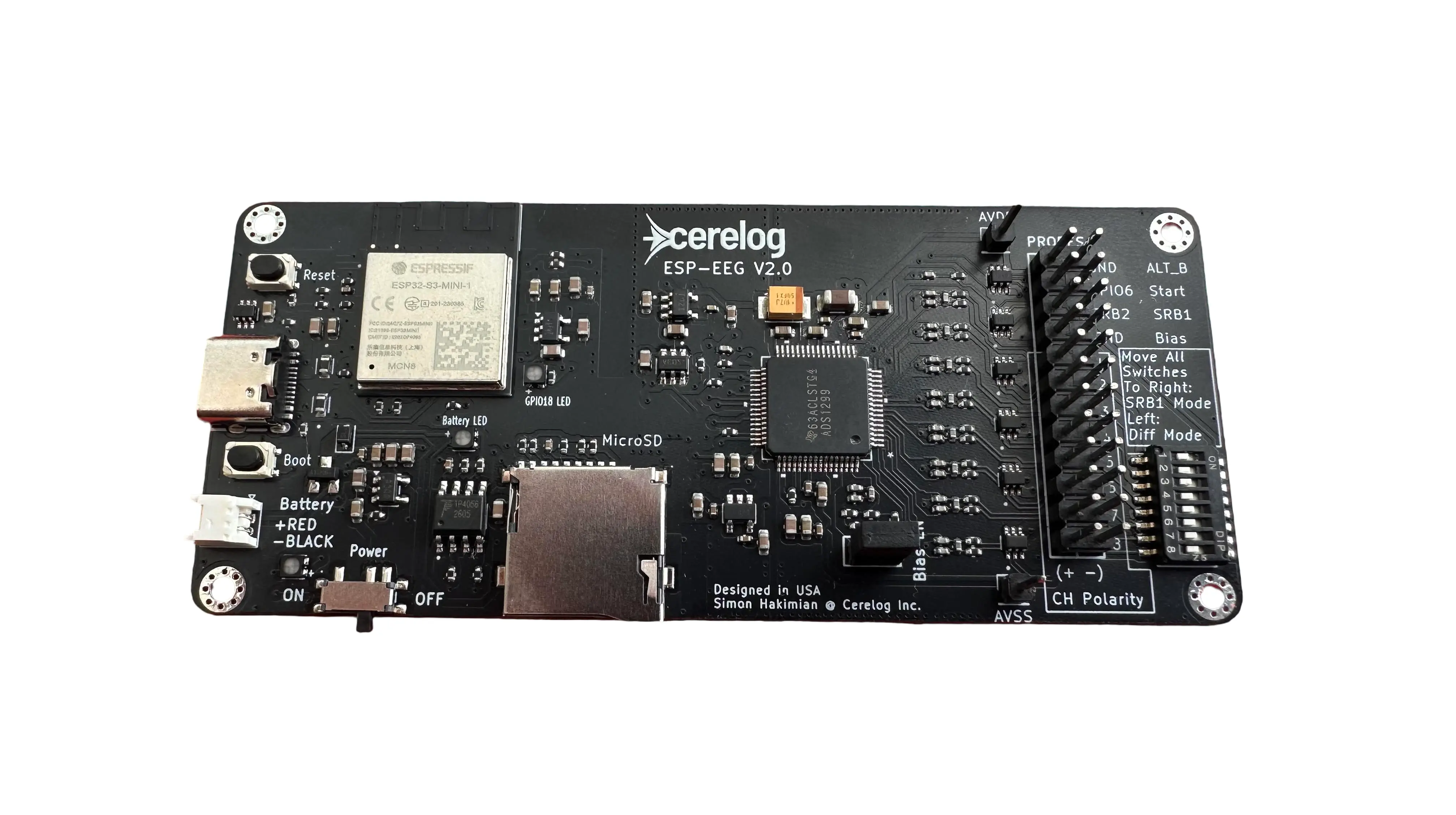
Cerelog ESP-EEG V2Next-Gen 8-Channel Brain Computer Interface Circuit Board
High Precision (ADS1299) 8 Channel Biosensing Board for Recording:
Easily Stream Data To:
Research Instrument — Not a Medical Device
About the ESP-EEG V2
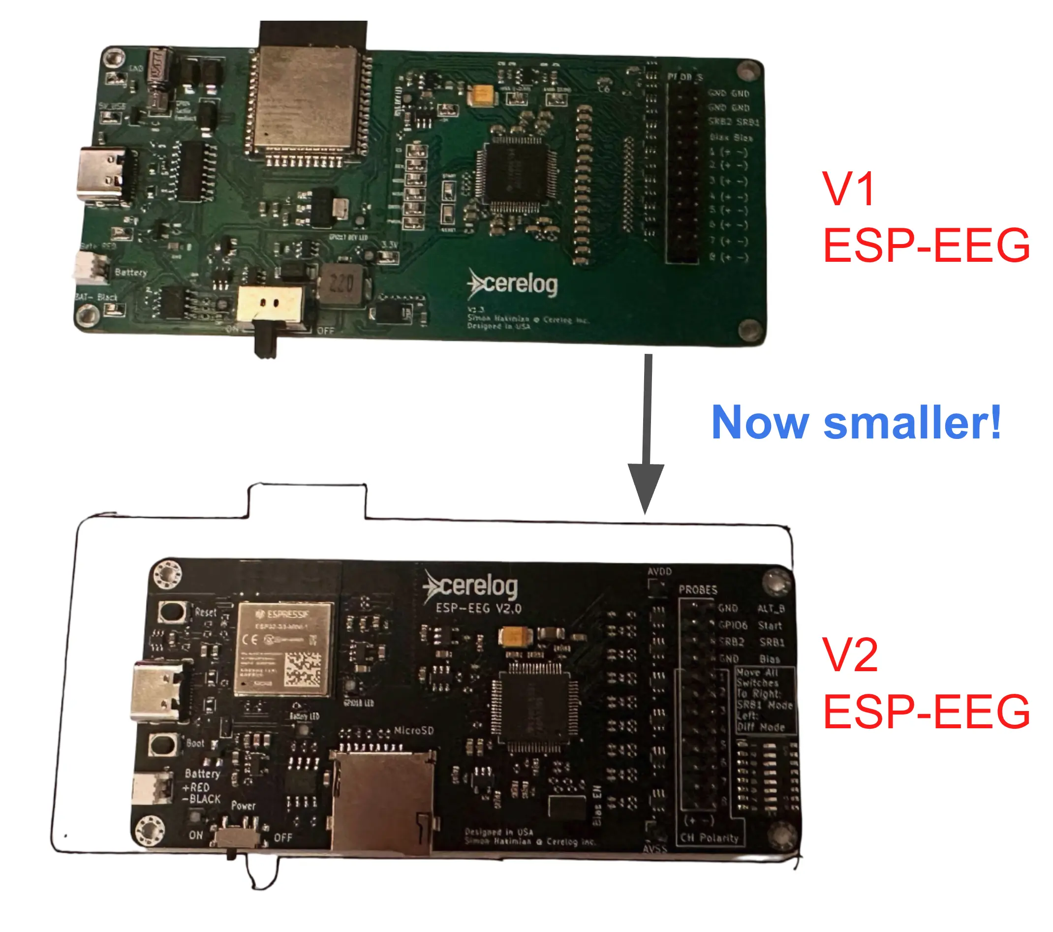
The Cerelog ESP-EEG V2 is the next generation of the 8-channel biosensing board, building on the proven ADS1299 architecture of the original ESP-EEG. Designed for EEG, EMG, ECG, and BCI research, the V2 features refined circuit design, True Closed-Loop Active Bias (Drive Right Leg / DRL) noise reduction, ESP32-S3-Mini dual-core processor with WiFi and USB-C connectivity, and onboard LiPo battery charging for untethered recording sessions.
The V2 remains fully compatible with BrainFlow, the OpenBCI GUI fork, and Lab Streaming Layer (LSL), ensuring a seamless transition for researchers already using the original board. Open-source firmware and schematics will be available on GitHub upon release.
(Existing V1 users will need to re-download the latest LSL and BrainFlow builds, as updates have been made to accommodate the V2 hardware.)
V1 vs V2 — What's New
Standalone Recording
Record CSV files to a microSD card without a computer with external LiPo battery*
In testing, a 2000 mAh battery recorded a corruption-free 1.7 GB file — ~22.4 hours of data — before the battery died. The 5000 mAh battery linked in the accessories section below should give a theoretical battery life of ~56.0 hours at an estimated ~89 mA draw.
*MicroSD card and battery sold separately
MicroSD usage instructions →| Feature | ESP-EEG V1 | ESP-EEG V2 |
|---|---|---|
| Onboard MicroSD (32 GB max) |
✗ No | ✓ Yes Record untethered — no computer required |
Cleaner Signal (vs V1)
Superior filtering and bias performance
Differential hardware filtering on top of the standard single-ended filtering —what most devices (including the OpenBCI Cyton) are missing to help eliminate common-mode noise.
| Feature | ESP-EEG V1 | ESP-EEG V2 |
|---|---|---|
| Common-Mode Filtering | Standard | Enhanced |
| Differential Input Filtering | ✗ No | ✓ Yes Rare — most devices on the market lack this |
| Bias Pin Design | Basic | Improved Active Bias |
Technical Explanation:
Texas Instruments' own ADS1299 documentation strongly recommends two separate input filters — a common-mode filter and a differential filter. Almost no board on the market ships both, and the reason is a design trap. The montage selector switch that swaps between referential and differential mode lives inside the ADS1299 itself. If you rely on that internal switch to change montage with a register write, you are forced to commit to one fixed input filtering arrangement that has to serve both modes. Faced with that choice, most companies keep the common-mode filter, skip the differential filter entirely, and ship it. It is a lazy solution, and it is paid for in performance.
Once the differential filter is gone, the remaining single-ended common-mode capacitors are forced to do the job of two different capacitors at once. They still have to roll off the high frequencies approaching the ~1 MHz band to prevent high-frequency aliasing — which was the differential capacitor's job — so they are forced to be large. That is exactly where the design breaks down. The differential capacitor is a single capacitor: large as it is, there is no second part for it to be mismatched against. A pair of large single-ended capacitors is a different story — real components carry real tolerance, the two never match exactly, and that imbalance exacerbates the very common-mode noise the filter was meant to remove. Common-mode-only filtering devices built this way, including the OpenBCI Cyton, are fighting their own input stage.
Cerelog was smart about this on the V2 and 16-Channel boards: we moved montage selection off the chip and onto physical hardware switches on the PCB. You still swap freely between referential and differential montage — but because we no longer depend on the ADS1299's internal selector, we are free to build the arrangement TI actually recommends. The big capacitor moves to the middle, differential position, where a tolerance mismatch has nothing to mismatch against and cannot hurt us, and smaller capacitors go inside the common-mode filters where they belong. The result is dedicated common-mode filtering and dedicated differential filtering — both present, each doing only its own job.
Before — common-mode only
After — Cerelog V2 & 16-Channel
This is the original optimized filtering arrangement that much of the BCI hardware industry was forced to design out just to keep register-based montage switching. Cerelog put it back. That is why these boards unlock far more of the ADS1299's real potential than hardware that stopped at single-ended filtering: stronger common-mode rejection, proper anti-alias protection near 1 MHz, and no self-inflicted imbalance in the input stage.
Enhanced Hardware Access
Battery monitoring exposed on-board via ESP32 GPIO for custom firmware
Battery life can be monitored by the user: IO0 (ADC1_CH0) senses the battery through a resistor divider network — multiply the measured voltage by 2 to get the real battery voltage.
Event sync trigger exposed on-board via ESP32 GPIO for custom firmware
Event sync trigger input: IO6 (ADC1_CH5) is broken out from the ESP32 for an external trigger — 3.3 V max, with a current-limiting input resistor. Modify the existing firmware to accept the trigger for tests that need a sync.
Hardware capability only — not coded into the default firmware. Intended for users modifying the firmware for custom applications.
Just like the OpenBCI Cyton, the trigger input is not opto-isolated — the user is responsible for the safety of whatever they plug into it.
Quick Montage Configuration
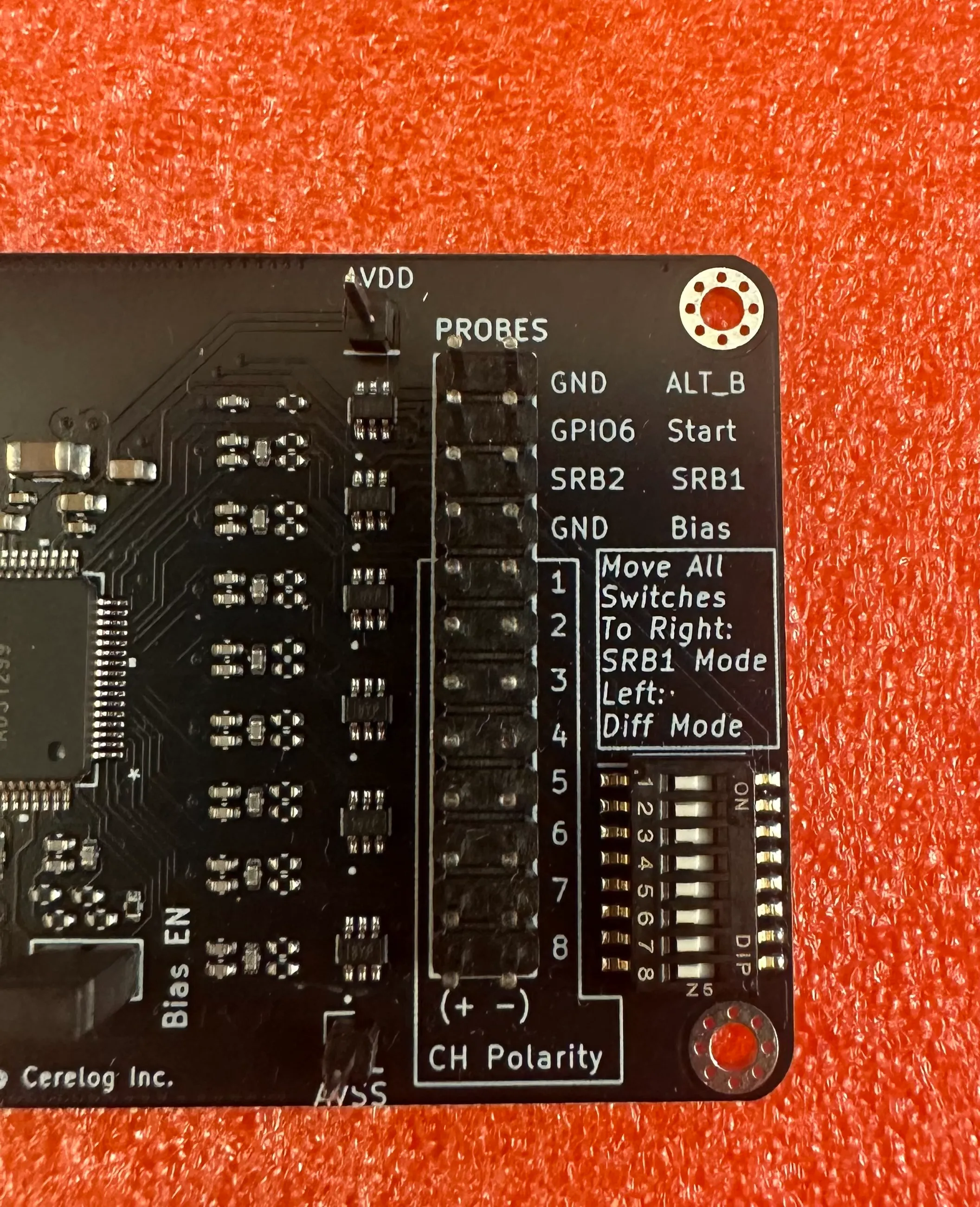
The board supports both a referential montage (SRB1) and a differential montage (CH+ / CH–), and you choose between them with the physical slider switches on the PCB — not in software.
The switches are somewhat recessed — use something like a pin or the tip of a pair of tweezers to move them, rather than your fingers.
V2 wiring instructions →Flexible Bias Pin Configuration
Default: True Closed-Loop Active Bias (DRL) — recommended for EEG and most EMG
The BIAS pin implements True Closed-Loop Active Bias (Drive Right Leg / DRL): it feeds a processed, inverted common-mode signal back through a dedicated electrode, actively cancelling interference such as 50/60 Hz mains hum. This is the best-performing configuration and the way the board ships — leave the jumper installed in the BIAS_EN slot and connect your bias electrode to the BIAS pin.
Optional: open-loop style bias via ALT_B — sometimes preferred for EMG
Some users prefer a more open-loop bias arrangement, which can occasionally suit EMG work. To try it, connect your bias electrode to the ALT_B pin instead and remove the jumper from the BIAS_EN slot. The two setups are mutually exclusive: ALT_B works only with BIAS_EN removed, and the BIAS pin works only with the jumper installed.
For normal use, keep the BIAS_EN jumper in place and use the regular BIAS pin — closed-loop active bias is the better-performing option. ALT_B is provided for users who want to experiment with alternative bias configurations.
📉 Superior Noise Reduction (Closed-Loop Bias)(All Cerelog Devices Feature)
Unlike many consumer EEG devices that use "open-loop" or passive grounding strategies, the Cerelog ESP-EEG implements a True Closed-Loop Active Bias (Drive Right Leg).
The Problem: Many competitors leave the bias feedback loop open, rendering the noise cancellation ineffective against movement artifacts and 50/60Hz hum. Their bias pin effectively becomes the average of the supply rails and acts as a ground on their device making the bias pin not function as effectively intended on the ADS1299 datasheet.
Our Solution: We utilize the full capability of the ADS1299 to measure the common-mode signal, invert it, and actively drive it back into the body.
The Result: A significantly lower noise floor and fewer artifacts, allowing for research-grade data capture even in non-shielded environments.
| Feature | ESP-EEG V1 | ESP-EEG V2 |
|---|---|---|
| Processor | ESP32-WROOM-32 Single-Core |
ESP32-S3-Mini Dual-Core Eliminates the slow serial bridge — native USB support unlocks higher throughput |
| ADC | ADS1299 8-Channel, 24-Bit |
ADS1299 8-Channel, 24-Bit |
| AVDD / AVSS Header Pins +2.5 V / –2.5 V ADC supply rails on header pins |
✗ No | ✓ Yes Powers user self-supplied active electrodes (ie; ThinkPulse* active electrodes) *Non affiliated 3rd party vendor |
Key Features (V2 Design)
- ✓8-Channel ADS1299 ADC — Texas Instruments 24-bit, research-grade analog front-end
- ✓ESP32-S3-Mini Dual-Core Processor — Bluetooth Low Energy (BLE) and WiFi connectivity, USB-C, and onboard LiPo battery charging
- ✓True Closed-Loop Active Bias (DRL) — Advanced noise reduction technique that feeds a processed reference signal back through a dedicated electrode
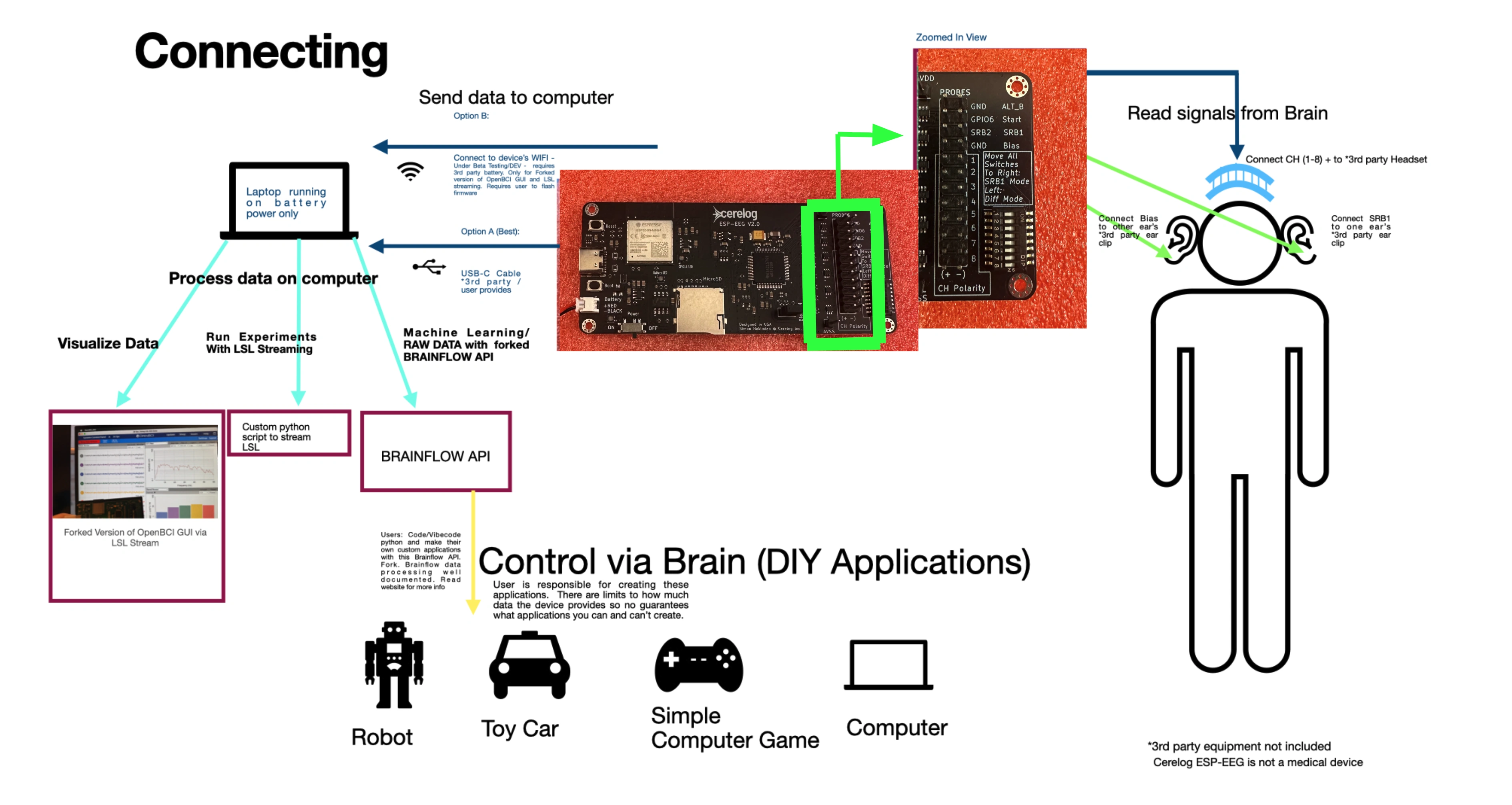
- ✓USB-C, Bluetooth LE & WiFi — Primary USB-C connection, plus Bluetooth Low Energy (BLE) and WiFi for LSL streaming to OpenBCI GUI fork
- ✓Onboard LiPo Charging — Untethered recording sessions with battery power
- ✓Open-Source Firmware & Schematics — Fully available on GitHub for inspection, modification, and community contributions
- ✓BrainFlow, OpenBCI GUI, & LSL Compatible — Works with existing research workflows and toolchains
Research-Grade Data at a Fraction of the Price:
Same gold-standard ADC (ADS1299) with modern architecture MCU (ESP32).
| Feature | Cerelog ESP-EEG V2 (8 CH) | OpenBCI Cyton ( 8 CH) |
|---|---|---|
| Chip | ADS1299 | ADS1299 |
| Data Resolution | 24 Bit | 24 Bit |
| Standalone? | ✅ YES | ✅ YES |
| Total Cost | $649.99 | $1,249* |
*All prices as of DEC 18, 2025
 Join the Discord Community server here to have your questions answered, fast support, and talk to other users
Video Demos
Demo of device used to control robotic hand
ESP-EEG Robotic Hand Controller — A demonstration of using the EMG capability of the ESP-EEG bio-signal sensor to control a robotic hand.
Playing pong game with eye movement (EOG) - user demo
ESP-EEG EOG Pong — A user demonstration of playing a Pong game using eye movement (Electrooculography) with the ESP-EEG bio-signal sensor.
Learn about the game development itself here.
To run: clone the repo and run python pong_game_brainflow.py --eog (on Mac use python3)
Playing Pong with device and SSVEP
ESP-EEG SSVEP Pong — A demonstration of using the SSVEP (Steady-State Visual Evoked Potential) capability of the ESP-EEG to play a game of Pong hands-free using brain signals. The board also supports P300-based BCI paradigms.
Video from one of our users
Product Overview Guide and Live Data Visualization
See the Cerelog ESP-EEG board in action. These demos showcase the real-time data streaming and BCI control capabilities.
Video demonstrating how to use product for real-time EEG signal data streaming and plotting.
*Shipping calculated at checkout
What You Get
- ✓ESP-EEG V2 PCB (8-channel, ADS1299)
- ✓Pre-loaded firmware
- ✓Open-source schematics & software
Looking for the current model? View ESP-EEG (V1) — Available Now
OpenBCI Gui (Forked) and LSL Compatible
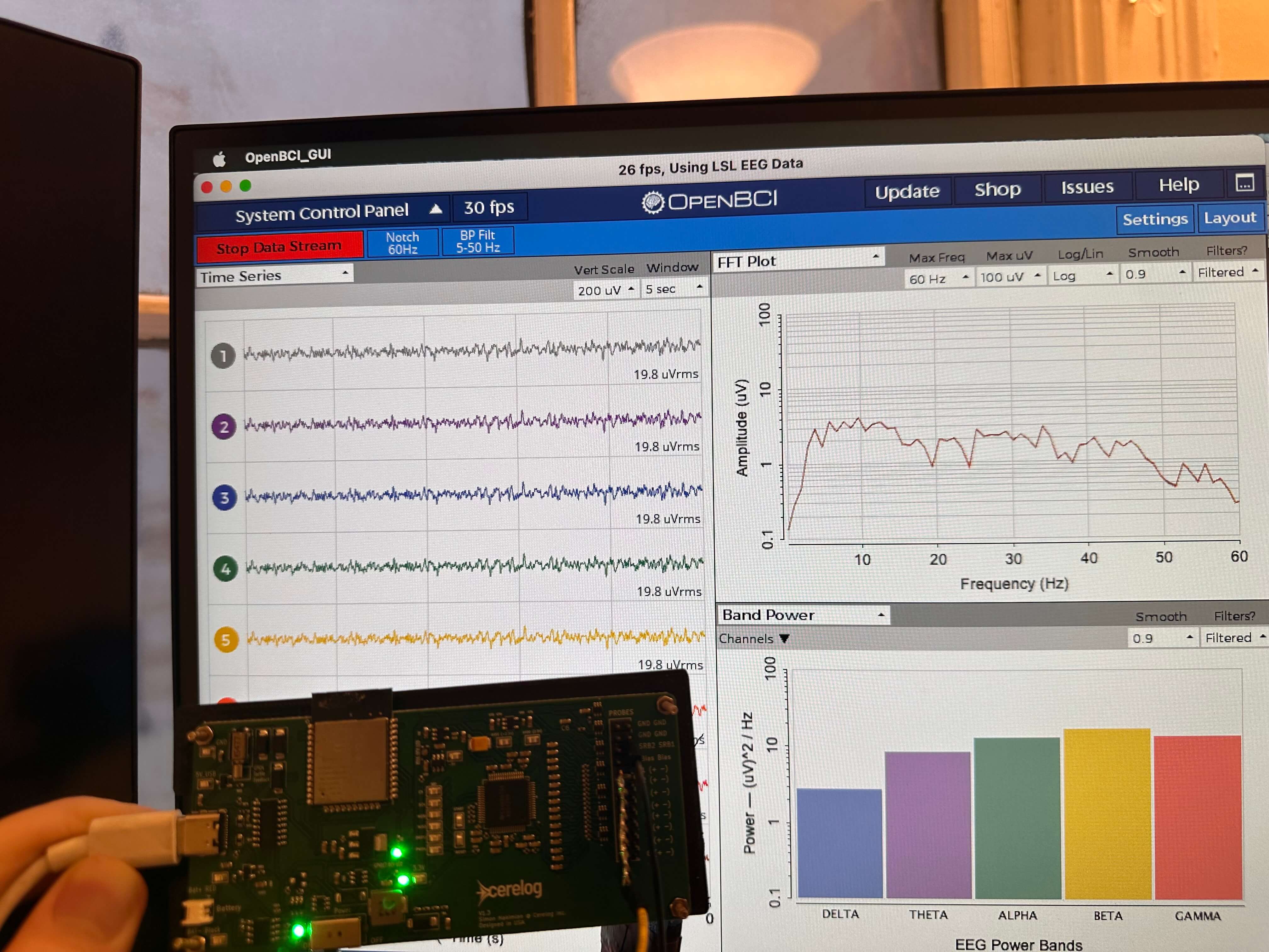
Visualize data easily and stream to other platforms.
Get Setup Script Here →Superior Noise Reduction
Closed-Loop Active Bias: Actively drives inverted common-mode signals back to the body.
Significantly lower noise floor & fewer artifacts.
Why Cerelog’s ESP-EEG?
Easy to use Software compatibility
Compatible with OpenBCI GUI (Custom fork) via Lab Streaming Layer protocol (LSL)
Setup instructions and LSL Custom Python connection script: OpenBCI GUI Setup Guide & LSL Script
A modified OpenBCI GUI has been forked above so you can visualize data easily and stream to other platforms. This works with its LSL streaming capability via a special Python script (in link above)!
The Cerelog ESP-EEG’s Python client software can stream data via the standard neuroscience software communication protocol Lab Streaming Layer. This means you can stream directly to your favorite neuroscience software or Matlab running on your laptop or remote computers, record data streams, and integrate ESP-EEG’s data with other data streams.
Stream data to BrainFlow API — Compatible for Powerful Data Analysis
The Cerelog ESP-EEG is fully compatible with BrainFlow, the industry-standard open-source library for acquiring and processing biosignals. This integration provides a unified, developer-friendly API to stream data directly into Python, C++, Java, and more, unlocking powerful tools for real-time analysis, signal processing, and BCI development.
- Custom instance of Brainflow Repo: Cerelog BrainFlow Repository for collecting data with the device.
Note: Test script to quickly view plot and acquire data -> Run ’Shared_brainflow-cerelog/python_package/cerelog_tests/filtered_plot.py’ from in above repo. (Must download and run with full Brainflow instance to use)
How to Connect ESP-EEG to BrainFlow
📄 Setup guide: Cerelog user guide — software setup & board usage
⚙️ BrainFlow instructions: GitHub /Instructions — detailed & always up to date (the setup guide above also covers BrainFlow scripting basics with the device — highly recommended)
🔗 Cerelog Main Repo: github.com/Cerelog-ESP-EEG/ESP-EEG
Quick Browser GUI Tester (Limited Support)
A single Python script that pipes data directly to a browser-based GUI — no complex setup required. It’s a legacy tool with limited ongoing support, but it’s a great starting point: it connects to the PCB over serial and plots your data live in the browser.
This script is especially useful for understanding how data is moving over serial in real time. That said, the BrainFlow script above is significantly easier to work with and is the recommended path for any serious data collection or analysis.
General Visualization Software and DemosPhantomLoop Integration — Browser Based Neural Decoder (Beta Testing)
A decoder is a small program — usually a machine-learning model — that looks at those signals and guesses what the person was thinking or trying to do.
A community-built browser-based decoder playground. Stream live EEG data from your ESP-EEG, run an ML model on it, and see predicted vs. actual outputs side by side — no local install needed. Built by community member yelabbassi; third-party.
Learn more about PhantomLoop →What's Included
- •1x Cerelog EEG Circuit Board
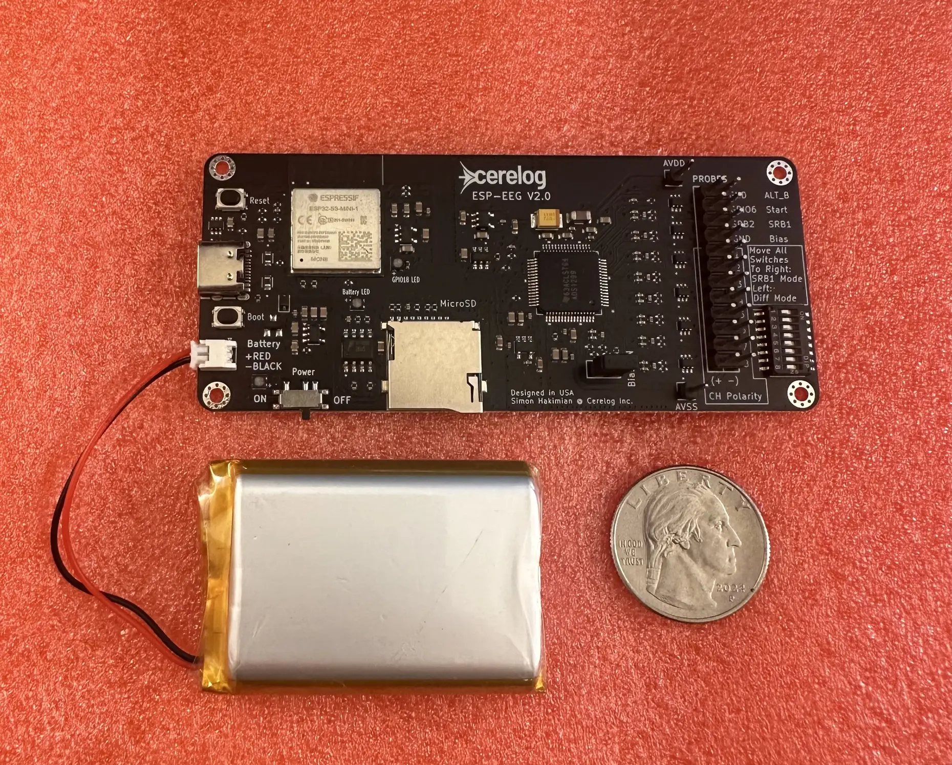
- !Battery not included. Please see compatible accessories below for recommended third-party battery options. Coin shown in photo is not included.
- !User must provide their own USB-C cable capable of data transfer.
- !Also not included: EEG Electrode Cap kit, required two sets of adapters for use with electrodes, and electrode gel. Please see 3RD party compatible accessories links below for recommended third-party accessories for use with the Cerelog PCB.
USB-C connection is the most reliable method and is fully supported.
Bluetooth Low Energy (BLE) and WiFi are both supported for wireless streaming to the OpenBCI GUI fork; BLE is the newer of the two and the recommended wireless path. WiFi mode requires an initial firmware flash — setup steps are in the GitHub Quick Start Guide. For BrainFlow-based workflows, USB-C is the recommended connection method.
Only use device with a laptop running on its own power supply, ensure it is not charging. Do not use this device with any computer plugged into mains power. This device does not feature isolation circuitry to protect from mains faults or power surges.
The Cerelog ESP-EEG is not a medical device nor is it intended for medical diagnosis. Read full page for all notices.
What's Included
- •1x Cerelog EEG Circuit Board
- !Battery not included. Coin shown in photo is not included.
- !User must provide their own USB-C cable capable of data transfer.
- !Not included: EEG Electrode Cap kit, adapters, and gel.
USB-C connection is the most reliable method and is fully supported.
Bluetooth Low Energy (BLE) and WiFi are both supported for wireless streaming to the OpenBCI GUI fork; BLE is the newer of the two and the recommended wireless path. WiFi mode requires an initial firmware flash — setup steps are in the GitHub Quick Start Guide. For BrainFlow-based workflows, USB-C is the recommended connection method.
Only use device with a laptop running on its own power supply, ensure it is not charging. Do not use this device with any computer plugged into mains power. This device does not feature isolation circuitry to protect from mains faults or power surges.
The Cerelog ESP-EEG is not a medical device nor is it intended for medical diagnosis. Read full page for all notices.
Required & Recommended Accessories
The following items are not included but are required for a full setup.
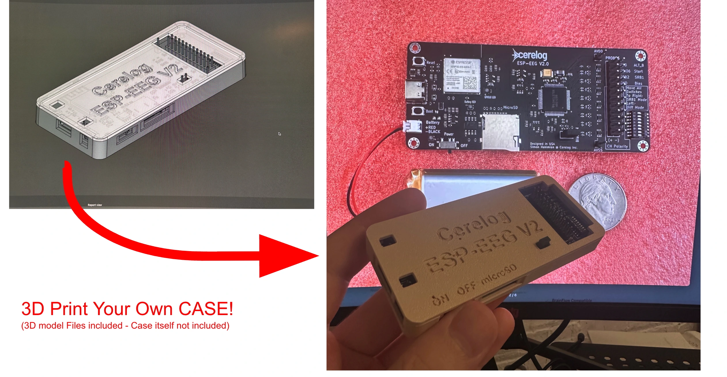
3D Print your own case
RecommendedEEG Electrode Cap Kit
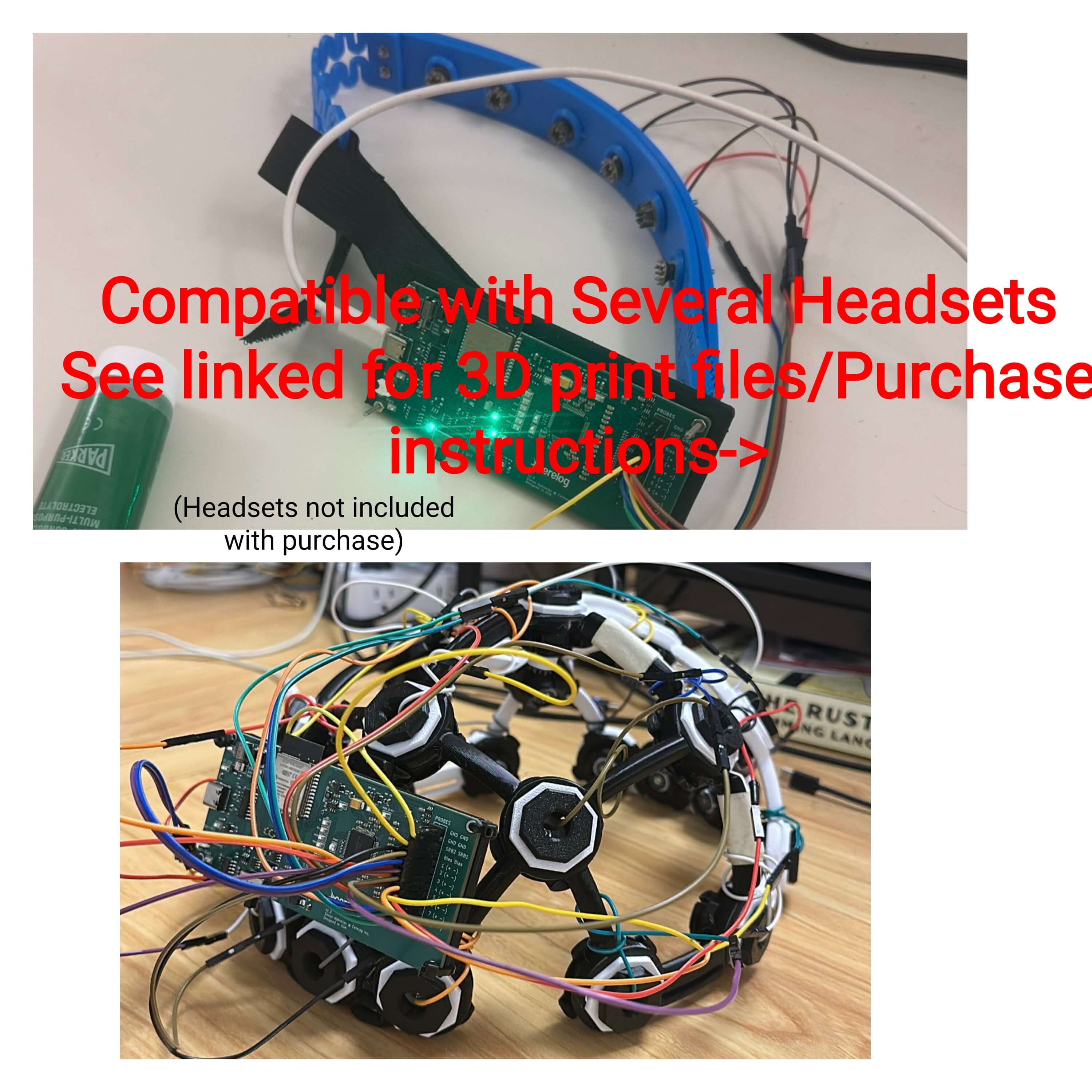
RequiredDIY Headset Alternatives
Ultracortex Mark III — Rigid 3D-Printed Cap
3D print your own headset using Ultracortex files + Cerelog adapter.
View Adapter FilesCereBRAH Soft-EEG — Community Soft Headband
A DIY soft EEG headband made from nylon webbing and elastic. Community-built, work in progress.
View Project DetailsElectrode Gel
RequiredProduct Demos
See the Cerelog ESP-EEG board in action. These demos showcase the real-time data streaming and BCI control capabilities.
Product Overview Guide and Live Data Visualization
Video demonstrating how to use product for real-time EEG signal data streaming and plotting.
Advanced Signal Integrity & Features
Active Bias Drive for Superior Noise Cancellation
The onboard bias probe actively works to cancel common-mode interference from sources like mains hum (50/60Hz noise). By feeding an inverted common-mode signal back to the user, it dramatically improves signal quality, allowing for clean, DC-coupled data acquisition in challenging environments. This is a critical feature for high-fidelity research that many other boards lack.
High-Fidelity ADS1299 ADC
At its core, this research-grade bioamplifier board utilizes an ADC capable of resolving signals down to 10µV peak-to-peak (1-50Hz). While real-world performance is subject to environmental noise and setup, this high-precision foundation ensures you capture the most subtle neural signals.
Flexible Electrode Montage Configuration
The board features an onboard slider switch that allows you to change montage modes without any firmware modification. Slide all switches to one side for SRB1 referential montage (each electrode measured against a single common reference), or slide them to the other side for differential montage. Do not modify the firmware montage setting — all montage switching is handled physically via the slider switches on the board.
Technical Specifications (ADS1299 Based)
Research Applications
The Cerelog EEG Circuit Board is a versatile, high-precision tool designed for advanced research applications including:
- •EEG (Electroencephalography) studies
- •EMG (Electromyography) measurements
- •ECG (Electrocardiography)
- •Brain-Computer Interface (BCI) development
- •Custom Computer Interface Development
Important Notice
This product is intended for research, engineering, and educational purposes only. It is not a medical device and has not been evaluated by the FDA. The product is not UL or FCC certified.
This evaluation board/kit is intended for use for ENGINEERING DEVELOPMENT, DEMONSTRATION, OR EVALUATION PURPOSES ONLY and is not considered by Cerelog Inc. to be a finished end-product fit for general consumer use.
We expressly disclaim any liability whatsoever for any direct, indirect, consequential, incidental or special damages, including, without limitation, lost revenues, lost profits, losses resulting from business interruption or loss of data, arising from the use of this product.
Disclaimer: The Cerelog ESP-EEG board is not a medical device nor is it intended for medical diagnosis and provided to you "as is," and we make no express or implied warranties whatsoever with respect to its functionality, operability, or use, including, without limitation, any implied warranties, fitness for a particular purpose, or infringement. We expressly disclaim any liability whatsoever for any direct, indirect, consequential, incidental or special damages, including, without limitation, lost revenues, lost profits, losses resulting from business interruption or loss of data, regardless of the form of action or legal theory under which the liability may be asserted, even if advised of the possibility of such damages.
Cerelog Inc. assumes no liability for the performance, suitability, or use of any third-party products linked or recommended on this website.
*Wireless data transmission may be subject to bandwidth limitations and environmental factors. By ordering, you acknowledge and agree to our Terms of Service, Privacy Policy, and Legal Disclaimer.
*By ordering, you acknowledge and agree to our Return Policy.
The Cerelog ESP-EEG Circuit Board is not intended for medical use and is not approved by the FDA to treat or diagnose any conditions. Please expand and read the above Important Notices section.
Background & Design Context
The Cerelog ESP-EEG was designed from the ground up to close a gap that has existed in the low-cost biosignal hardware space for years: boards that use the right ADC chip but cut corners on every surrounding circuit decision. The ADS1299 is a genuine research-grade component — the same part found in instruments costing tens of thousands of dollars — yet many low-cost implementations treat it as a commodity part and ignore the reference design guidance that makes it perform well. The ESP-EEG was built by following that guidance closely, particularly around the bias drive topology and power supply filtering, rather than around minimizing BOM cost.
Choosing the ESP32 as the host microcontroller was deliberate. It handles SPI communication with the ADS1299 reliably over USB-C at the board's operating sample rate, while the onboard radios handle wireless. The ESP32-S3-Mini's Bluetooth 5.0 / Bluetooth Low Energy (BLE) support was added recently and is the better of the two wireless options; the WiFi radio enables LSL streaming to the OpenBCI GUI fork. The board ships with USB-C firmware pre-loaded. As with any microcontroller-based acquisition system, some data throttling applies and occasional packet loss is possible depending on the host environment. The USB-C interface handles the majority of current workflows reliably, and the LIPO charging circuit means the board can be untethered from a computer during a recording session when battery operation is preferred.
From a software standpoint, the decision to integrate with BrainFlow and publish a fork of the OpenBCI GUI rather than building a proprietary application reflects a philosophy of meeting researchers where they already are. Most academic labs already have Python environments with NumPy, SciPy, and MNE installed. Rather than asking users to learn a new toolchain, the ESP-EEG plugs into the infrastructure they already trust. The BrainFlow integration in particular means that any script written for another BrainFlow-compatible board can be adapted to work with the ESP-EEG with minimal modification.
The open-source firmware and published schematics serve a dual purpose: they allow technically capable users to audit exactly what the hardware is doing, and they create a foundation for community contributions. Several community-built tools — including the PhantomLoop neural decoder interface — have already emerged from users who were able to examine the data protocol directly. The Discord community exists specifically to lower the barrier for researchers who are domain experts in neuroscience or BCI but are not hardware engineers, connecting them with users who can help with setup questions quickly.
The board is positioned as a research instrument rather than a consumer product, and that distinction matters practically. It ships without a case by default because many research applications call for integration into a custom headset, enclosure, or experimental rig where a generic case would just get removed. STL files for a printable reference enclosure are available in the GitHub repository for users who want a standalone housing without designing their own.
*Shipping calculated at checkout
What You Get
- ✓ESP-EEG V2 PCB (8-channel, ADS1299)
- ✓Pre-loaded firmware
- ✓Open-source schematics & software
Looking for the current model? View ESP-EEG (V1) — Available Now
*By ordering, you acknowledge and agree to our Terms, Privacy Policy, Legal Disclaimer & Important Notice and Return Policy.
*(International Orders) Recipient responsible for all import duties, VAT, and broker fees. Estimate your costs (HS Code: 8517.79.0000). Duty/tax estimates are for informational purposes only and may differ from actual charges.
*Please note: We are currently unable to ship this product or sell to customers of New York state.
Research-Grade Data at a Fraction of the Price:
Same gold-standard ADC (ADS1299) with modern architecture MCU (ESP32).
| Feature | Cerelog ESP-EEG V2 (8 CH) | OpenBCI Cyton ( 8 CH) |
|---|---|---|
| Chip | ADS1299 | ADS1299 |
| Data Resolution | 24 Bit | 24 Bit |
| Standalone? | ✅ YES | ✅ YES |
| Total Cost | $649.99 | $1,249* |
*All prices as of DEC 18, 2025
Join the Discord Community server here to have your questions answered, fast support, and talk to other users
Required & Recommended Accessories
The following items are not included but are required for a full setup. These are links to third-party vendors.
EEG Electrode Cap Kit
RequiredA professional electrode cap is necessary for placing electrodes on the scalp. This is a recommended third-party option.
View Cap KitWe are not affiliated with this vendor.
▼ Cheaper Alternative — Gold Cup Electrodes
On a budget? Gold Cup Electrodes with conductive paste are a lower-cost option. No extra adapter is needed — they plug directly into the Cerelog board.
Note: The user is responsible for determining how to secure the electrodes to the body.
View Gold Cup Electrodes View Ten20 Electrode Paste3rd party vendor — we are not affiliated with this vendor.
DIY Headset Alternatives Don't have money to buy an entire headset? Make your own...
Ultracortex Mark III — 3D-Printed Rigid Cap Third-party 3D-printed EEG cap with Cerelog adapter plate
As a cost-effective alternative, you can build your own data acquisition cap by using the 3D print files for the Ultracortex Mark III headset, a third-party project.
To make this headset compatible with the Cerelog ESP-EEG PCB, you must also print our special adapter plate (using the .stl file) and secure it to the headset with bolts or zip ties.
View Cerelog Adapter Plate FilesThe springs for the headset can be hard to find at a good price. For the soft main springs, we have found that 12mm OD, 0.6mm Wire Size, 20mm Free Length, Silver Tone springs (Size: 12x0.6x20mm) from Amazon work well.
View Recommended SpringsPlease note: We are not affiliated with the third-party vendors who provide the Ultracortex files or the recommended springs.
CereBRAH Soft-EEG — Community-Built Soft Headband A low-cost, DIY soft EEG headband made from nylon webbing and elastic
A community contributor designed the CereBRAH Soft-EEG — a wearable EEG headband that holds dry electrodes at standard 10-20 positions. Unlike rigid caps, it's built from 50 mm elastic band and hook-and-loop nylon webbing joined by staples, so it flexes to fit the head, packs flat, and is cheap to build and repair.
Work in progress: This project is still under active development. Designs, cut lengths, parts, and instructions may change.
View CereBRAH Soft-EEG Project DetailsCommunity project — not tested or verified by Cerelog. Not a medical device.
Touch-Proof Adapters
RequiredThese adapters are essential to connect the electrode cap to the Cerelog board. You must purchase one set for an 8-channel referential setup.
View AdaptersWe are not affiliated with this vendor.
Electrode Gel
RequiredConductive gel is needed to ensure a low-impedance connection between the electrodes and the scalp for high-quality signals. Do not use if you are allergic to any ingredients.
View Electrode GelWe are not affiliated with this vendor.
LIPO Battery
Recommended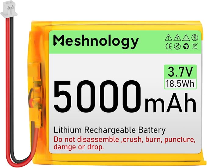
For portable, untethered use, a LIPO battery is recommended. The board has an onboard charging circuit for a 3.7V battery with a Micro JST 1.25 Plug (1.25mm).Board-side connector: Molex PicoBlade, manufacturer product number 0530480210.
Alternatively, a standard 5V USB power bank with a USB-C cable can also be used for untethered operation.
View BatteryNote: Third-party product. Verify specs.